Vertical Glandless Sealless Pump

Vertical Glandless Sealless Pump
VGP – SERIES PUMPS
(Vertical Glandless / Sealless Pumps)
M.O.C – U.H.M.W. – P.E.
The V.G.P.Series pumps in normal hydraulic terms does not differ from any conventional
centrifugal pump.The pump is designed in such a way that the liquid which would normally try to pass through the point, where the impeller drive shaft enters the backplate(stuffing box) is diverted and returned as a controlled flow to the suction tank.The need for any seal is eliminated by allowing the leakage liquid to escape through the Overflow connection of the overflow chamber.
Working Principle
The liquid entering suction flow around the impeller casing and leaves through the delivery under pressure.Between the annular gap of upper rotor casing and impeller some leakage liquid escapes to the overflow chamber.
The auxiliary impeller (expeller)prevents the leakage liquid going further up and canalises it through out -lrt in the overflow chamber.
These pumps are ideally suited for continuous operation and for all scrubbing application.The pumps always work with a negative suction.
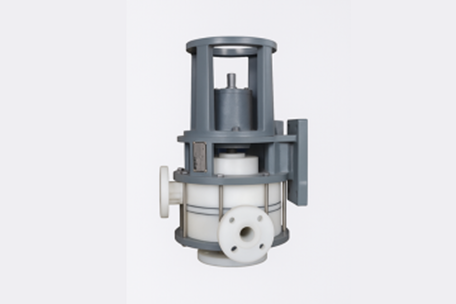
Components
- 1. Suction
- 2. Delivery
- 3. Overflow
- 4. Impeller
- 5. Lower Casing
- 6. Upper Casing
- 7. Upper Body
- 8. Thrower
Applications
Phosphoric acid plants :
H3PO4, H2SO4, HF and their mixtures with or without solids (gypsum) up to 40% conc.
Gas washing plants :
Scrubbed liquids containing F, CL, SO2, Ammonia gases etc. With solids Replace hastally.
Rayon plants :
Spin bath solution (H2SO4, ZnSO4, Na2SO4 etc.)
Caustic soda plants :
Chlorinated brine, conc. HCL, H2SO4 etc. Other application are in metal refineries, pickling Installations, paper and fertilizer plants-in fact all chemical process industries.
Range of Performance
In general the range cover flow up to 100m3/hr. and discharge head up to 50 meters.
Installation & Operation
Priming Requirements
- Where Low Level priming is not required.
- Where Low Level priming is required.
- Where priming at all levels is required.
- Where priming at all levels is required without re-circulation.
- For deep variable head storage tanks or where suction lifts must be kept to minimum.
Installation Guidelines
Overflow Configuration
All installations must have the overflow from the pump to the supply or priming vessel:
- Straight
- Have no restriction (valves etc.)
- Slope down - 1 in 20 or more
- Preferably 12" long maximum
Valve Requirements
- Valves 'A' to be of the free flow type.